| Version 6 (modified by , 15 years ago) ( diff ) |
|---|
Second Microtest Set
This data set consisted of two exposures taken with the default voltages, one with the microtest 05 voltages (SW_L = default - 1.0 V, SW_H = default - 1.0 V), and six others that vary only SW_L or SW_H (with the other set to the default value). To study the impact of these changes, I reduced the data as before, and found the best fit lines in the dx and dy offsets as a function of instrumental magnitudes. The data were binned using 0.1 magnitude bins, and the fit performed between -14 and -12 (other fits were performed using ranges (-16:-14) and (-12:-10), but are not shown here).
The following images show the best fit slopes as a function of voltage in both dx and dy directions, with the dy data providing a control. These show convincingly that SW_L has little effect on the slope within this range, but SW_H values below -0.5 decrease the slope significantly. Since the microtest 05 voltages changed both SW_L and SW_H, there is a jump between the two slope values at SW_L = -1.0V. The two points that comprise this jump are from microtest05 (the smaller slope) and from microtest18 (which varied only SW_L and so still has a larger slope). Comparing the 2-phase and 3-phase devices show that the 3-phase devices have generally acceptable slopes regardless of SW_L and SW_H.
| OTA33 / 3-phase | OTA34 / 2-phase |
 | 
|
Mosaic of all OTAs. Click to see most legible version that fits under the wiki 2MB filesize limit.

Image changes
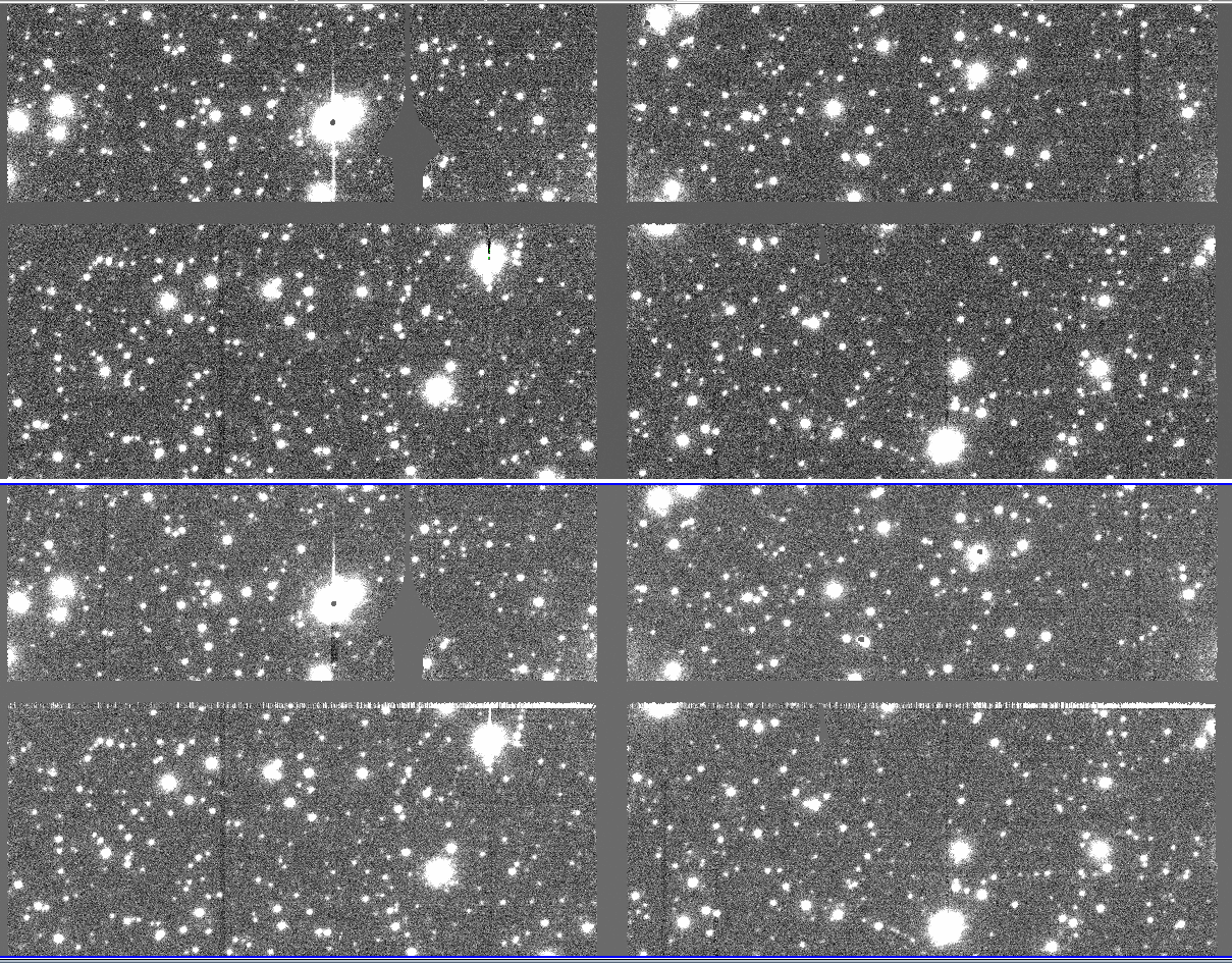
There does appear to be a small change in the images due to this voltage change. OTA36 row 6, and OTA47 row 5 and 6 show bright bands in the top ~6 pixels. The following image shows OTA36/row6 with the default settings (top) and with SW_H changed by -1.0V (mt19, bottom):

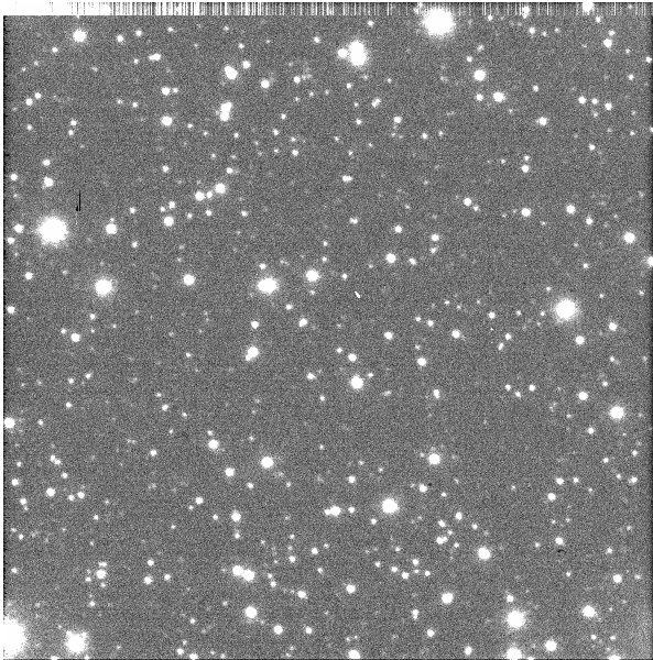
The raw images show that this is not a result of the nonlinearity correction, as it is present before this is applied. It also is present in all rows of the detector, but is shorter on the other rows, and falls into previously masked regions. Image is of OTA36/xy66

Attachments (6)
- SW_tests_OTA33.png (5.7 KB ) - added by 15 years ago.
- SW_tests_OTA34.png (6.4 KB ) - added by 15 years ago.
- SW_tests_montage_big.png (1.9 MB ) - added by 15 years ago.
- merged_data (122.9 KB ) - added by 15 years ago.
- mt_difference.png (2.0 MB ) - added by 15 years ago.
- top_noise.png (501.9 KB ) - added by 15 years ago.